
Proper Shaft Fits for Precision Drive Components
When sizing high performance drive components, proper shaft fit is an important consideration in helping to maintain concentricity and balance in the rotating equipment. In v-belt drives, chain drives and other low-cost / low-speed systems, designers often give little thought to shaft fit. Many manufacturers of these types of low cost drive components are simply relying on a shaft key and set screw to transmit torque and retain the hub on the shaft, and other types of misalignment absorbing elements help to take up any eccentricity resulting from a relatively large clearance between the shaft and the bore. But when it comes to high-performance / high-speed drives and “smart” motors, such as servo and steppers, shaft fit becomes increasingly important.
When researching a possible vendor for zero backlash components with engineered clamping systems that can be assembled by hand, it is imperative that they are able to provide a shaft tolerance as well as a published chart which verifies the shaft and bore fits required. As a general rule of thumb, the overall diametrical clearance between the shaft and the bore should be around 10-50 µm (.0004-.0019”) for smaller diameter shafts, and as shaft diameters increase beyond 80mm (3.150”), larger clearances become allowable, and more annulus is required around the ID of the bore to ensure easy installation. If the fit is correct, a bit of oil is all that is required to easily slide a hub onto a shaft.

Many engineers are inclined to specify interference fits for high performance drives, which in a solid hub design would require either sub-zero cooling of the shaft and / or, more commonly, heating of the bored and keyed hub. This type of fit dates back to times before frictional clamping systems became well established in the power transmission industry, and is intended to eliminate problems associated with loose shaft fits and backlash. Requiring this type of work can create a maintenance and installation problem, and is not necessary in most modern applications incorporating engineered clamping systems. But the importance of precision shaft fit remains when it comes to frictional clamping style hubs.
Frictional Clamping Hubs
In the case of clamping collarstyle hubs, which offer the advantage of very easy installation and removal, if the fit clearance is too large between the shaft and bore, once clamped, the hub can become eccentric to the shaft. This can cause an imbalance and or misalignment issue in addition to the potential for failure of the driveline. In self centering clamping systems, often used for high speed / high power systems, excessive fit clearance can reduce the transmittable torque of the shaft hub connection. But with proper shaft fits and screw tightening torques applied, they offer superior performance to simple keyway hubs, and far easier handling than interference fit hubs.
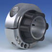 (clamping collar)
 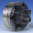 (self-centering clamping system)
Manufacturing Standards
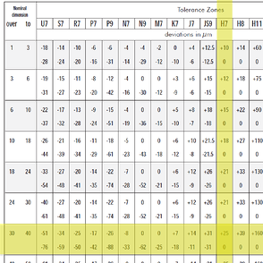
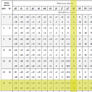
There are several standardized shaft tolerance charts commonly used in industry such as ANSI B4.1-1967 (R2004) for imperial units and ISO tolerance system per DIN 7160 (8.65) for metric units. Precision drive components should have a clearance fit which is just out of range of a transition fit such as an H7/h6 fit per DIN 7160 (8.65) chart. For example on a 32 mm diameter shaft, this would mean that the shaft could be 0-16 µm under 32mm. The bore could be 0-25 µm over 32 mm. This would result in a diameter difference of 0-41 µm (.0000-.0016”).
If the shaft and bore were both the same size, assembly would be difficult. In practical manufacturing, this would almost never happen. A good machinist would normally use a H7 go/no-go plug gauge and an h6 go/no-go ring gauge. The go portion of the plug gauge would not practically fit into the bore by hand unless the bore was slightly larger than 12 mm exactly. Vice-versa, with the ring gauge and shaft, when checking a turned part with a ring gauge, it would not fit by hand unless the shaft was a bit smaller. If either no-go plug or ring gauge fits, the parts are scrapped. This method of machining/checking shafts and hubs results in parts with a precise fit which can be assembled by hand.
For more information on proper shaft fits and precision couplings for high performance drive applications, contact applications@rw-america.com.