
Balanced High Speed Precision Couplings
Balanced High Speed Precision Couplings
As a manufacturer of precision couplings, we spend quite a bit of time on high speed applications. Here are a few basic tips about coupling balance.
A properly balanced drive component should not induce excessive vibration into the drive line. This means that the mass of the component rotating about the axis of the shaft must be evenly distributed in such a manner as to maintain an even centrifugal force about the axis of rotation. The magnitude of the centrifugal force generated by a rotating component varies with the location of the center of mass of the drive component versus the axis of rotation and orientation of the moment of inertia.

A simple way to think of static balance about an axis is to imagine playing on a see-saw in a playground. Two people of equal mass can sit at an even distance apart from each other and maintain balance. Or one person of a heavy mass can sit close to the pivot point and a person of a light mass can sit far away from the pivot point and maintain balance. A rotating mass works essentially the same way. As an object with constant mass moves away from the axis of rotation, the centrifugal force increases exponentially. In physics, this is simply illustrated with a moment of inertia calculation (I=mr^2).
In practical manufacturing, rotating parts are made with evenly spaced jaws, spokes, etc. Balancing comes into play when manufacturing processes cause imbalance or additional parts such as clamping screws or shaft keys are added. Adding or subtracting mass in one area of a part causes an imbalance. This must be corrected by adding or subtracting mass on the opposite side of the part. Manufacturers most often do this by drilling holes into the part near the outside diameter so that less material will need to be removed resulting in a more structurally sound part versus removing a lot of material near the axis of rotation.
Precision parts such as machined coupling hubs are designed with the balancing holes in a location so they can be produced in quantity in a numerically controlled process without balancing each part individually. This provides cost savings and consistency to customers. Quality small to medium sized machined hubs should come with a speed rating of about 10,000 RPM. Many of these hubs can be finely balanced for speeds between 30-80,000 RPM depending on size. The larger in diameter and more massive a hub becomes, the lower the practical balance speed will be.
Other considerations such as torque transfer at high speed need to be examined as well. Centrifugal forces at high speeds will begin to open clamping hubs for example. Since the screws of clamping hubs are normally tightened to a torque which takes them near their tensile yield, the effects of centrifugal forces applying additional screw tension as the clamp opens must be considered. This is why in medium to large sized hubs, conical clamping rings are often favored, since they offer better symmetry and better stress distribution as a result of the forces applied to them at high speed.
R+W makes a lot of standard and custom couplings for high rotational speeds, some of which rated to handle speeds in excess of 150,000 rpm.
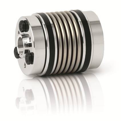
The coupling shown at left is one of our miniature designs. Higher torque versions are available on request. Contact us with your high speed coupling requirements and get the ultimate connection.
