
Mounting a Sprocket or Pulley to a Torque Limiter
Mounting a Sprocket or Pulley to a Torque Limiter

As a manufacturer of torque limiters for indirect drives, we are often asked to provide some assistance when it comes to mounting the torque limiter inside a drive sprocket, pulley, or gear. R+W does offer to provide torque limiters as a complete package, with the drive attachment pre-mounted according to customer specifications, but we are also happy to provide customers with some guidance when it comes to doing this on their own, including providing machining drawings for a do-it-yourself or third party project. In this article we’ll focus on mounting a roller chain or timing belt sprocket to a torque limiter, as they represent the vast majority of requirements for indirect drive torque limiters.
The process is really straight forward, and can usually be performed in any machine shop with a milling machine and a lathe. Once the correct torque limiter body size has been selected, based on the required bore diameter and disengagement torque, it must be compared dimensionally with the size of sprocket being used, in order to determine whether it can be mounted directly to the torque limiter, or if it will need to be offset mounted. While a drive sprocket with a smaller diameter than the torque limiter output flange can be offset mounted on a separate bearing, and attached using an adapter plate as needed, it is usually easier and less expensive to choose a sprocket that will fit directly.

Most quality torque limiters include a bearing (1) between the base of the clutch and the output flange. This helps to ensure that the driving and driven portions of the torque limiter are properly guided within the rotational axis after disengagement. In order to protect the bearing from moment loading, the belt or chain tension (2) needs to be well centered over the bearing, unless it will be supported by an external bearing, as is the case in offset mounted systems. Centering the tension over the bearing in the torque limiter often requires that an additional pocket be machined into the drive attachment, so that the torque limiter can be sunk into drive attachment to a depth that places the bearing underneath the drive medium (i.e. belt or chain). R+W offers an allowable load centering range, in terms of a distance from the end face of the torque limiter. This load centering range, dimension “S” from the R+W safety couplings catalog, is the range in which the center of the chain or belt must reside for smooth, sound operation.
Once the dimensions have been selected, machining the mounting features into the sprocket or pulley is fairly straight-forward. First an inside pilot diameter is bored into the sprocket on a lathe. This bore should be precise to match the centering diameter on the torque limiter output flange. The centering diameter is referred to as dimension “E” in the R+W safety couplings catalog, and it is the contact surface which ensures that the sprocket will be well centered around the drive axis. An ISO H7 tolerance is recommended for the pilot diameter, which normally runs between half a thousandth to just under two thousandths of an inch oversized from the nominal diameter, depending on the size, with the larger tolerances applying to larger diameters. The pilot bore should also be concentric to the pitch diameter of the pulley or sprocket. Lathe jaws with a flat grip for the tips of the sprocket teeth and a machined recess to hold the face plane of the sprocket perpendicular to the axis of rotation allow for a simplified setup. 
Next, any relief needed for centering the chain or belt tension over the bearings in the torque limiter is turned into the sprocket’s face. This diameter must be greater than dimension “G” from the R+W safety couplings catalog, and is less critical than the pilot bore diameter, since it is only for clearance. It is important however that the sprocket or pulley is square in the lathe chuck, since the turned face in the resulting pocket needs to rest flat against the face of the torque limiter output flange in order for the drive to run smoothly.
Finally, the clearance hole bolt circle is drilled into the sprocket on a milling machine or drill press. The size and number of holes can be taken from dimension “H” in the catalog, and the bolt circle diameter taken from dimension “F” in the catalog. Using a rotary table makes this process quick and easy. These holes can be counter-sunk or counter-bored to save axial space if installation space is at a premium.

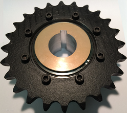
Once the sprocket or pulley is finished, it is ready to be mounted to the torque limiter output flange. Inspect the machined surfaces to ensure that they are clean and free of nicks, burrs, and debris. Slide the drive attachment over the centering pilot on the torque limiter and rotate, while applying gentle pressure, to ensure a proper fit. Little to no relative movement between the drive sprocket or pulley and the torque limiter output flange should be possible, aside from rotation. Insert the mounting screws and ensure that they are finger-tight. Evenly tighten the screws in a crosswise pattern, applying 1/3, 2/3, and finally 3/3 of the recommended tightening torque for the size and type of screw being used.
The drive attachment is now machined and properly mounted, and is ready for installation.
As always, don’t hesitate to contact your coupling experts with questions about proper sizing, selection, and handling of torque limiters and safety couplings.


