Introduction to Industrial Disc Pack Couplings
Maintenance-free and torsionally stiff connecting elements for smooth stable running
For many decades engineers have turned to the flexible disc pack coupling for applications requiring maximum reliability and uptime, minimizing wear on adjacent equipment, and eliminating the need for lubrication or maintenance of the coupling itself. Prior to the invention of the disc coupling, flexible couplings nearly always included either gear teeth that required periodic lubrication, or rubber and plastic parts that degraded over time and required replacement. Further, as industrial processes became more sophisticated in the latter portion of the twentieth century, the need to improve coupling balance became critical as a means of reducing shaft vibration to protect the bearings and seals of the connected equipment – something the flexible disc coupling helped with a great deal. Over time the use of disc couplings has grown into a wide variety of applications, with numerous machine designs taking advantage of their unique characteristics. This introductory article provides a brief overview of the basic construction of industrial disc couplings and what gives them the performance and longevity that so many engineers value.
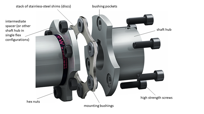
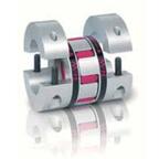
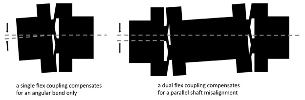
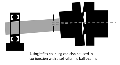
Flexible disc packs are composed of thin sheet metal shims, generally stamped or laser cut in a ring shape with a series of mounting holes; normally 6-8 but more or fewer are also used, depending on the size of the coupling, with the smallest designs commonly using 4 and with any number of holes being used for the very largest of disc couplings. The shims are stacked together and held in place with bushings, and the resulting disc pack is bolted into the coupling system. Misalignment compensation depends on the flexibility of the shims themselves, and generally the larger the stack, the greater the overall stiffness of the disc pack in terms of both torsion and bending. Centering of the disc pack in the coupling can be accomplished by different means, with one common method being precision machined pockets in the adjacent mounting flanges which hold the disc packs concentrically in place by their bushings. The disc packs are mounted to their respective hubs with the bolted joints alternating between the driving hub and the driven hub. The portions of the disc pack bridging the distances between the respective bolted joints provide the flexibility and allow a single disc pack connection to pivot and compensate for an angular bend while transmitting rotation and torque. A single disc pack is generally rigid in shear, meaning that it cannot compensate for misalignment between two independently bearing supported shafts, unless used in conjunction with a second disc pack to make the opposite angular bend and complete the parallel offset. The exception to this rule is when a single disc pack is used in conjunction with a self-aligning ball bearing, which replaces the second disc pack in providing the second angular freedom of movement. The greater the distance between disc packs, the larger the parallel misalignment which can be compensated for at a given bending angle.
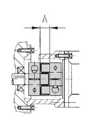
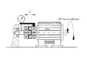
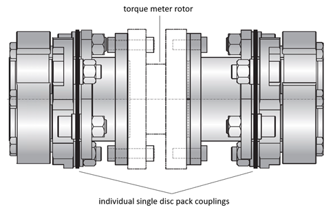
The stiffness in shear of a single disc pack provides one of the keys to smooth running at high speed. Most flexible couplings have some level of softness in the radial direction, which means that centrifugal forces will more easily deform the flexible element when rotating at higher speeds, leading to instability, and making vibration more likely. In contrast disc couplings have a unique ability among flexible coupling systems to hold all of their components rigidly within their rotational axes, including any spacers, drive shaft tubing or other components which might be mounted in series between the two flexible joints. This makes them an excellent choice for high speed balancing. A further advantage of the radial stiffness of a single disc pack is its ability to support intermediate devices. Most commonly this intermediate device is a torque meter, used widely in test stands and other applications which require condition monitoring. This allows for the torque meter to become an integral part of the coupling system, held in concentric rotation by the radial stiffness of the single disc pack coupling mounted on each of its driving and driven faces.
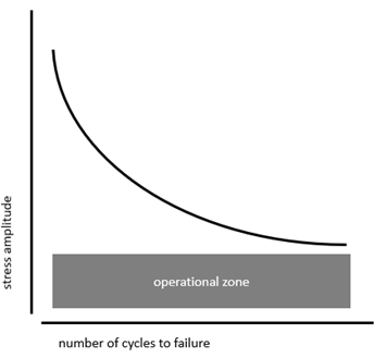
Also related to rotational speed is the number of bending cycles a disc pack can tolerate before failure. Because they have no wear or moving parts, no abrasion occurs over the course of a single rotation, and misalignment compensation is accomplished purely through the bending of the sheet metal. Steel components are generally considered to possess long term fatigue strength when able to withstand 107 load cycles of a given stress amplitude. Because industrial disc couplings are generally rated for misalignment and torque conditions which can be withstood for at least this number of cycles, they are considered fatigue resistant for a service life approaching an infinite number of rotational bending cycles – key to their reputation for maintenance free reliability.
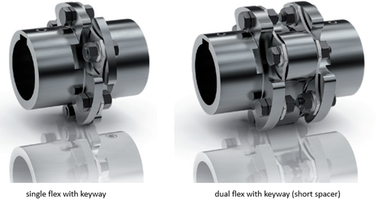
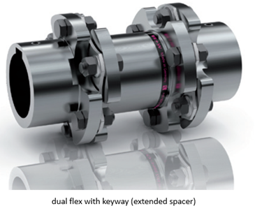
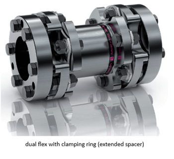
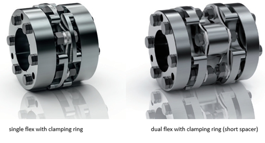
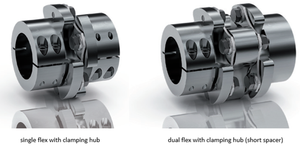
Because of the diversity of applications into which flexible disc couplings are implemented, a wide variety of configurations exist, and most manufacturers offer customization and special features. Below is a short overview of common standard designs, the features of which can often be readily made into combinations of different hub styles and with the extended spacers cut-to-length, making it by no means an exhaustive listing.
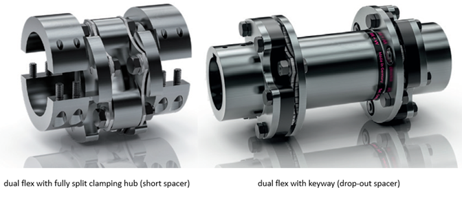
The drop-out spacer coupling shown as the last item in the overview is available with a specific set of features to make the coupling compliant with API-610 which is a standard developed by the American Petroleum Institute to address design reliability in centrifugal pumps and couplings. Instead of the disc pack bolting directly to the shaft hub, it bolts to an intermediate guard ring that in turn bolts to the shaft hub. This creates a spacer cartridge which allows for easy installation and removal without any need to move the shaft hubs. This drop out feature is useful for gaining access to pumps and gearboxes for maintenance with minimal effort. The intermediate guard rings also extend through the center holes of the disc packs, providing a safety catch to prevent the intermediate tube from being thrown in the event of unexpected disc pack failure. Use of this drop out spacer feature has become popular in applications beyond those found in the oil and gas industry, such as in rotary test stands and other devices where the need for semi-frequent coupling disassembly is anticipated.
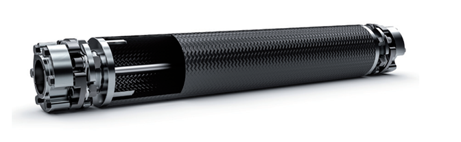
Another useful customization is a configuration with a carbon fiber drive shaft tube. This allows for industrial disc coupling systems to span longer distances at higher speeds. The combination of light weight and high stiffness of carbon fiber tubing allows for smooth running in extended shafting applications with minimal imbalance or whipping contributed by the tube. Pictured below is an example of an industrial disc coupling configured with carbon fiber tubing as well as a special plumbing system that allows fluid to be passed through the center of the coupling to provide lubrication for machine tool applications
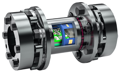
Perhaps the most interesting add-on feature for disc couplings is a newly developed remote sensor system which can be integrated into the spacers. These new sensor systems provide wireless transmission of torque, speed, vibration and thrust load data in real time via Bluetooth connection to either a smartphone or tablet with a special app, or to a wireless gateway for integration of performance data transmission into existing control systems. This technological advancement is of significance to engineers and operators who previously experienced some difficulty in monitoring data at critical locations in the drive line, having needed to either estimate loads or run time consuming and expensive tests for periodic monitoring of loads in the past.
Depending on the configuration industrial disc couplings continue to be the best option for heavy-duty transmission in applications that require the highest reliability and uptime, spanning of long distances between shafts, and combinations of high power and high speed. While a variety of off-the-shelf configurations are available for standard applications, customization also abounds. Consulting with manufacturer applications engineers is always the best starting point, and R+W is ready to assist with an evaluation of project and performance requirements, and to help determine the best solution for any application. Contact us at info@rw-america.com for details.

R+W has been designing and manufacturing high performance flexible shaft couplings and torque limiters since 1990 and continues to expand its product portfolio with each passing year. With a reputation for performance, quality, and customization, it is considered by many to be the top precision coupling manufacturer in the world.