About this blog

This is where you give the visitor a brief introduction to both this blog and your company. Keep the intro pithy and punchy.

Subscribe to Email Updates

Recent Posts

Posts by Topic

see all

Blog

Solving Problems with Torsionally Stiff Couplings

Posted by Andy Lechner on Wed, May 22, 2013 @ 17:08 PM


SOMETIMES YOU NEED A FLEXIBLE COUPLING THAT'S TORSIONALLY STIFF

One of our customers in Michigan has a short application story we'd like to share with you.  It provides a great example of how precision bellows couplings can help solve machine performance problems.


 Bellows Coupling White Paper


 MICHIGAN CUSTOM MACHINES, NOVI, MI (http://www.michigancustommachines.com/)

Engineer: Brian Nugent

"Michigan Custom Machines builds end of line functional test machines, primarily for the diesel and automotive industries.  This particular application required a 400 lb flywheel to mimic the inertia of a diesel engine driveline.  The flywheel was mounted to a shaft that needed to be coupled to a custom camshaft which is actuating a fuel injector.  

mcm photo

One of the biggest challenges on this application was stiffness of the coupling.  We have history with this application and have found if the coupling has wind up, even though it is zero backlash, it will affect how the test is performed by allowing the instantaneous rpm to droop momentarily within part of a revolution.

For this application I called (R+W) direct, also passed information back and forth through e-mail to him.  Prior to this application I have always known who R+W was, mainly through word of mouth within the custom test machine community and the internet.

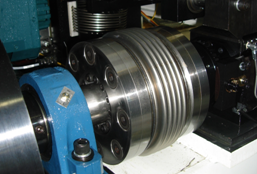
We used a Model BK1/6000/XX.  It was a custom model - the adapters were custom to fit the different shaft sizes and the shaft locks we used.

It was known when sizing this coupling, the BK1/6000/XX could not handle as much torque as a previous disc type coupling used, but the stiffness was higher.  After installing the BK1/6000/XX, an instrument was used to see how much phase change is seen during operation from one side of the coupling to the other.  The BK1/6000/XX showed 1/3 of the phase difference or wind up compared to the previous couplings used.  This resulted in more consistent testing of the fuel injector.”


bk1

CUSTOM MADE TO FIT

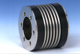
Normally for this 6,000 Nm application we would have worked with our BK3/6000 shaft coupling, but it became clear as we were checking the fits that a special solution would be needed in order to accomodate existing space restrictions.  So it was decided that this solution would be based instead on our BK1/6000 basic bellows coupling. One of many custom mounting arrangements we work with here at R+W is to insert special flanges inside the bellows so that keyless locking devices can be used without extending the coupling length.  Flat head cap screws allow us to maintain a low profile while still maintaining the structural integrity needed for high torque transmission.

If you have a difficult shaft coupling application you'd like some help with, don't hesitate to contact our applications engineering group at applications@rw-america.com. 


 Bellows Coupling White Paper

Tags: test stand coupling, torsional stiffness, torsionally stiff coupling, coupling torsional stiffness, torsional rigidity, drive couplings, bellows coupling, torsion resistance, torsion resistant coupling, torque test coupling, torque sensor coupling

A Quick Refresher on Converting Coupling Torsional Stiffness

Posted by Niilo Nykanen on Fri, Apr 05, 2013 @ 11:12 AM

  Bellows Coupling Sizing Program

A Quick Refresher on Converting Torsional Stiffness Values 

Customers often ask us for a bit of assistance in comparing torsional stiffness values between flexible couplings made by manufacturers using Imperial versus SI units.  This may be considered rudimentary to some but a quick refresher never hurts.  

Any drive component which transmits torque will twist a bit when torque is applied. For example, if a shaft was marked on each end very precisely notched on the same plane along its axis, the notches would move apart as torque is applied.shaft deflection


The amount they move apart is proportional to the applied torque. Therefore, torsional stiffness is called out in units of torque applied per angular unit of twist. North American manufacturers tend to use a variety of different units while Europeans typically use Newton meters per radian.  

The Conversion

I've provided an example conversion below.  In this example calculation, we are converting a given stiffness value of 76000 N*m/Rad  to in*lb/Deg , this will require a bit of unit conversion. As many of us may remember from college chemistry, we are allowed to multiply ratios of different units that mathematically equal 1 to cancel unwanted units and convert to the desired ones. Below, we can see that the units in red cancel. In just a couple of steps the desired units emerge.

equation 1

equation 2 

Or conversely, converting a value given in in*lb/Deg to N*m/Rad:

equation 4

equation 5 

Coupling Stiffness

As we see in the example, if we we’re comparing flexible couplings, the top one would be more torsionally stiff. Having a high level of torsional stiffness is not always desirable, especially if someone wanted to use the flexible coupling to damp vibration.  However in many cases machine builders need to maximize torsional stiffness in order to reduce settling times in highly dynamic applications or to maximize rotational positioning accuracy.  In the case of flexible shaft couplings, elastomeric (elastic) couplings are typically used for vibration damping, and metallic couplings are used for maximizing torsional stiffness. 

This example can be used for comparing any multitude of different units as long as the correct conversion ratios are employed. 

 Bellows Coupling Sizing Program

Tags: torsional stiffness, torsionally stiff coupling, coupling torsional stiffness, torsional rigidity, torsion resistance, torsion resistant coupling