About this blog

This is where you give the visitor a brief introduction to both this blog and your company. Keep the intro pithy and punchy.

Subscribe to Email Updates

Recent Posts

Posts by Topic

see all

Blog

Basics of Angular Acceleration and Rotational Moment of Inertia

Posted by Niilo Nykanen on Fri, Jun 14, 2013 @ 14:22 PM

 Bellows Coupling White Paper


Angular Acceleration and Moment of Inertia in Machine Design 

As a provider of flexible drive couplings and ball detent safety clutches, we are often asked to provide a bit of assistance in calculating application torques, especially for customers looking to retrofit existing equipment.  In order to aid in the process of estimating torques, we'll review one of the basic calculations used to estimate the torque required to accelerate a rotating mass to a certain speed over a given time.  

Angular acceleration (α) can be defined as angular velocity (ω) divided by acceleration time (t). Alternatively, pi (π) multiplied by drive speed (n) divided by acceleration time (t) multiplied by 30. This equation yields the standard angular acceleration SI unit of radians per second squared (Rad/sec^2). The equation below defines the rate of change of angular velocity.

 equation 1

ω = angular velocity in the standard SI unit of radians per second (Rad/sec), 1 radian = 57.3 degrees

t = acceleration time in seconds

π = 3.1416

n = drive speed in revolutions per minute RPM


In the next example, angular velocity will be calculated for acceleration from 0 to 60 RPM in one second. Note that 2π radians per second = 60 RPM.

 calculation 2


This calculation is very useful in machine design because angular acceleration multiplied by rotational moment of inertia equals torque.  Keep in mind that the exact moment of inertia can be difficult to calculate based on complex geometries in real drive lines, and other variables such as friction are not considered in the next calculation.  Nonetheless it is still very helpful in approximating torque requirements or establishing baseline minimum values for component sizing purposes. 

 calculation 3

J = moment of inertia in kg∙m2

T= torque in N∙m

N= force in Newtons

kg= mass in kilograms

m= lever arm radius in meters


In the final example below we will use the angular acceleration we found above to calculate torque on a flywheel with a 1 meter radius and 1000 kg mass. 

 calculation 4

As we can see, if a flywheel with a 1 meter radius and 1000 kg mass were to be accelerated to 60 RPM in one second, it would require 3141.59 Newton meters of input torque.


I hope you found this refresher on calculating angular acceleration to be helpful.  If you have questions pertinent to the sizing and application of shaft couplings or safety clutches, feel free to contact our applications engineering department.


applications@rw-america.com


Bellows Coupling White Paper

Tags: rotational moment of inertia, acceleration torque, angular acceleration, motor acceleration, drive acceleration

Taking Advantage of Coupling Configurability

Posted by Niilo Nykanen on Thu, May 30, 2013 @ 16:05 PM

 Bellows Coupling White Paper


Configurable coupling systems save time and money

Many machine builders are well aware of the advantages of using configurable components in the design stages. As projects progress, specifications often change and builders must adapt components to fit new constraints. Drive and electrical components must be flexible to adapt to new operating parameters or machine chassis dimensions. Electrical designers often make use of DIN rail mounted devices which can be interchanged quickly on the production floor or in the field. Circuit breakers, fuses, and power supplies can be easily changed out in the event that a different motor or sensor is installed. From the mechanical perspective it is usually coupling elements which need to be changed to adapt to new dimensions.  This is why QD or similar bushings are typically used with V-Belt sheaves.  If drive speeds change, a fairly quick sheave swap is all that is required. If a new gearbox or actuator needs to be installed, drive couplings in various lengths and bore diameters are often required in order to help get everything tied together.  Finding direct drive couplings with compact dimensions and creative mounting configurations is normally fairly easy.  But in some cases layout changes involve longer distances between mechanically connected equipment, requiring something a little more specialized.


BELT DRIVE


 Belt drive or direct drive

With longer distances between rotating components, designers are often in a position to choose between belt or chain driving, and using a direct drive line shaft system.  A direct drive line shaft coupling typically provides for stiffer power transmission than belts, which can be especially advantageous in applications that require precision timing and positioning or frequent changes in rotational direction. Line shaft couplings are also low maintenance compared with belts which need to be changed at regular intervals, just like car tires for optimal performance. But in the past there were occasionally major drawbacks to using direct drive line shafts over belts in some applications.  Assembly with steel shafting and standard couplings generally requires intermediate support bearings and is not very well suited to higher drive speeds over long distances.  Most preassembled torque tube styles of line shaft couplings are also built to order rather than being stocked by many large industrial supply companies. In the past a typical prefabricated torque tube style line shaft would need to be rebuilt if length or shaft sizes changed. 


old style line shaft


New configurable line shaft couplings

In more recent years, prefabricated, variable length, telescoping line shaft couplings have been brought to the industrial market in order to address the growing trend toward designing with direct drives. A variable length line shaft with removable hubs solves the issue of shaft sizes and lengths changing (within adjustment range) as a machine is built or upgraded. With a variable length line shaft, the overall length can be changed in minutes by simply loosening and tightening a couple of machine screws. Jaw style hubs or flange mounted bellows coupling hubs can be swapped out with stock parts in less time than it takes to change a v-belt sheave and re-tension belts. Additionally, common size adjustable line shaft couplings are stocked by many distributors and ready to ship with hubs just like sheaves and belts.


Adjustable Line Shaft Coupling


This new take on configurable coupling component technology ultimately saves cost in labor and/or materials over time. While newer components produced in smaller quantity can have higher pricing up front, they can actually lower the cost of maintenance and overhaul down the road. Making use of a more precision product can also help to increase the rate at which a product is manufactured. As we all know, increased productivity and lower service costs ultimately decrease the time over which a return on initial investment is seen. This makes money for our employers, which is something I’ve found they enjoy universally.  


Bellows Coupling White Paper

Tags: spacer couplings, line shaft, telescoping shaft, jack shaft, drive shaft, line shaft coupling, adjustable coupling, torque tube

Solving Problems with Torsionally Stiff Couplings

Posted by Andy Lechner on Wed, May 22, 2013 @ 17:08 PM


SOMETIMES YOU NEED A FLEXIBLE COUPLING THAT'S TORSIONALLY STIFF

One of our customers in Michigan has a short application story we'd like to share with you.  It provides a great example of how precision bellows couplings can help solve machine performance problems.


 Bellows Coupling White Paper


 MICHIGAN CUSTOM MACHINES, NOVI, MI (http://www.michigancustommachines.com/)

Engineer: Brian Nugent

"Michigan Custom Machines builds end of line functional test machines, primarily for the diesel and automotive industries.  This particular application required a 400 lb flywheel to mimic the inertia of a diesel engine driveline.  The flywheel was mounted to a shaft that needed to be coupled to a custom camshaft which is actuating a fuel injector.  

mcm photo

One of the biggest challenges on this application was stiffness of the coupling.  We have history with this application and have found if the coupling has wind up, even though it is zero backlash, it will affect how the test is performed by allowing the instantaneous rpm to droop momentarily within part of a revolution.

For this application I called (R+W) direct, also passed information back and forth through e-mail to him.  Prior to this application I have always known who R+W was, mainly through word of mouth within the custom test machine community and the internet.

We used a Model BK1/6000/XX.  It was a custom model - the adapters were custom to fit the different shaft sizes and the shaft locks we used.

It was known when sizing this coupling, the BK1/6000/XX could not handle as much torque as a previous disc type coupling used, but the stiffness was higher.  After installing the BK1/6000/XX, an instrument was used to see how much phase change is seen during operation from one side of the coupling to the other.  The BK1/6000/XX showed 1/3 of the phase difference or wind up compared to the previous couplings used.  This resulted in more consistent testing of the fuel injector.”


bk1

CUSTOM MADE TO FIT

Normally for this 6,000 Nm application we would have worked with our BK3/6000 shaft coupling, but it became clear as we were checking the fits that a special solution would be needed in order to accomodate existing space restrictions.  So it was decided that this solution would be based instead on our BK1/6000 basic bellows coupling. One of many custom mounting arrangements we work with here at R+W is to insert special flanges inside the bellows so that keyless locking devices can be used without extending the coupling length.  Flat head cap screws allow us to maintain a low profile while still maintaining the structural integrity needed for high torque transmission.

If you have a difficult shaft coupling application you'd like some help with, don't hesitate to contact our applications engineering group at applications@rw-america.com. 


 Bellows Coupling White Paper

Tags: test stand coupling, torsional stiffness, torsionally stiff coupling, coupling torsional stiffness, torsional rigidity, drive couplings, bellows coupling, torsion resistance, torsion resistant coupling, torque test coupling, torque sensor coupling

Elastomer Jaw Couplings: Not All are Created Equal

Posted by Niilo Nykanen on Tue, May 14, 2013 @ 09:03 AM


Elastomer Jaw Couplings:  not all are created equal

ek picture

Today’s mechanical drive components market is flooded with a wide variety of direct drive couplings. Many folks working with or designing drives are not familiar with the different technologies or differences in quality and precision between manufacturers. One prime example is with elastomeric jaw couplings. Elastomer jaw couplings have been around for 100 years or more. Most of these couplings use two hubs and an elastomeric spider between the jaws to transmit torque. Although they look essentially the same, the applications can vary greatly.


traditional jaw coupling 2

Traditional Jaw Couplings

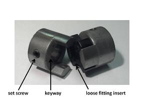
Much of the market by volume of units sold consists of low manufacturing cost cast hub couplings with a rubber spider element.  These hubs are used in drives such as conveyors and centrifugal pumps turning in one direction where precise shaft position is not important.  Torque is usually transmitted accross the hubs by means of a keyway locked down with a set screw.  Many of the machine frames are formed and welded to loose tolerances.  The coupling design has plenty of play between the spider insert and jaws to accomodate shaft misalignment.  This design is optimal for producing machinery where labor time to align shafts is cost prohibitive, and they are ideal for less demanding applications. 


precision jaw coupling

Precision Jaw Couplings

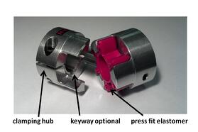
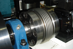
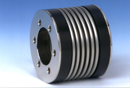
A somewhat smaller part of the market volume is precision backlash free or low backlash elastomeric couplings. The hubs of these couplings are generally machined from solid stock with clamping features incorporated into them for wear free and play free frictional connections to the shafting.  This can eliminate the need for keys and keyways and also enhance performance while improving longevity.  


concentricity measurement


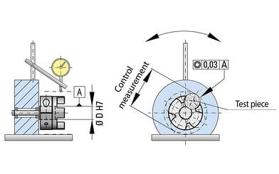
The machined hubs typically also come with curved jaws held to a very tight level of concentricity in reference to the bore. Measuring concentricity from the jaw to the bore is what ensures smooth transfer of rotation from one jaw set to the next. 


ek insert

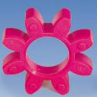
Wear resistant polyurethane inserts are then put through a secondary “match molding” process to smooth out any inconsistencies on the driving lugs, before being press fit into the hubs for a preloaded zero backlash assembly. 


Being based on the same principle of mounting a resilient element between the jaws of two metallic hubs, they look similar, but are quite different in some key characteristics.  Because the hubs are precision machined from solid bar stock, they are naturally more expensive than a cast or sintered hub.  But considering that both coupling styles are relatively inexpensive, the cost differences are often far outweighed by the benefits in situations where high torques or shock loads must be transmitted through a small space envelope, as can happen in many pumping, conveying, crushing and grinding applications to name a few, or in cases where dynamic motion needs to be transmitted smoothly, like in servo and stepper motor driven machines.  In the latter situations the precision concentricity and backlash free characteristics, and not only the stronger material condition of the hub benefit the user and the process.  


Shaft alignment

One of the assumptions being made with this design concept is that that a higher value will also be placed on the overall quality of the drive line assembly, which always includes precision alignment.  It is not uncommon for someone to switch to a precision elastomer jaw coupling and hear an audible clicking as the equipment runs. Because the elastomeric spider element is preloaded in the hubs and is a slightly harder material, it will rub on the metal surfaces audibly if there is significant shaft misalignment. Although lubricant can be used to address the clicking, eventually the elastomer segment may need replacement.  But when alignment is addressed they can be wear-free for a theoretically infinite service life.  

NEMA frame mounted motor


Many motors, gearboxes, linear actuators and pumps have precision centering features already incorporated into their mounting frames by the manufacturer for this very reason. When the coupling is installed inside a housing or bracket which takes advantage of a centering feature on both pieces of coupled equipment, then alignment is normally within the allowable limits for the precision variety of elastomer coupling.  


foot mounted motor


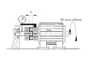
When no such feature exists, then alignment must be checked manually.  There are several approaches which can be taken to address this potential issue. For a single elastomer element coupling the shafts need to be precisely aligned with dial indicators or laser alignment systems in case the shaft alignment is not inherent to the mechanical assembly.  


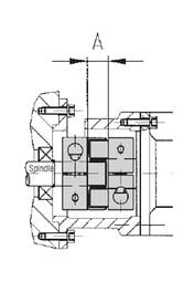
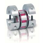
For situations where space is tight, split hub couplings are available to be installed laterally after the manual alignment check has been performed and any necessary adjustments have been made. 

 ekh


convex elastomer

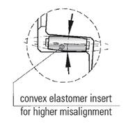
Then, in cases where precision manual alignment is just not practical, there are other options.  Many manufacturers make the urethane elastomer segment available with a convex tooth geometry, which allows for a rolling action as the coupling hubs rotate under angular misalignment. 


ekzWhen two are used in series with a coupling spacer, the ability to compensate for parallel shaft misalignment is magnified to many times greater than with the single element version, allowing for simple visual shaft alignment, while at the same time maintaining the benefits of relatively low inertia, zero backlash and high torque density.  


While these two different shaft coupling styles may look more or less the same, small differences in materials and manufacturing processes can mean big differences in terms of the end result.  When considering making the switch from traditional to precision varieties of elastomer insert jaw couplings, consider discussing your requirements with the manufacturer, and make sure to check all of the specifications to get the best coupling for your unique situation.

  Elastomer  Coupling Sizing Program

Tags: drive couplings, jaw couplings, flexible couplings, pump coupling, elastic couplings, elastomer couplings, spider coupling

Vibration Damping in Drive Couplings

Posted by Niilo Nykanen on Wed, May 08, 2013 @ 08:01 AM


Vibration damping couplings:  sometimes bigger is better


vibration damping couplings

A customer sizing an elastomer insert coupling recently asked us if using a larger body size would provide better vibration damping.  In a word, the answer was, yes.  Vibrations in machine shafts come from a wide variety of sources. Machines that crush and shred materials can impart quite a bit of vibration into the drive line and prime mover. These types of machines can cause motors and mechanical driveline components to fail prematurely if proper damping measures are not in place.  Conversely, driving components, especially internal combustion engines, can impart severe vibration down the driveline.  While R+W specializes in vibration damping couplings for electric motor drives, the concept of increasing driving inertia for smooth continuous rotation is most easily explained and widely understood in terms of internal combustion engines.


flywheelOne of the oldest methods mechanical designers have used to damp vibrations is employing a flywheel. This device is still widely in use, in many parts of industry. Using laws of basic classical mechanics, “a body in motion tends to stay in motion, while a body at rest tends to stay at rest,” designers know that it is difficult to change the rotating velocity of a massive, high inertia flywheel easily. This is why a flywheel is used on the output shaft of many combustion engines, since they tend to continue rotating smoothly rather than jerking severely every time a cylinder fires. A large drive coupling or belt pulley would have the same effect. Piston air compressors often have massive cast iron sheaves driving them for this reason. 


In situations where inertia, space and power consumption are not of concern, it can be beneficial to use shaft couplings with larger and heavier hubs than are necessary to simply transmit the torque.  At R+W we have machined flywheel features directly into steel coupling hubs on many occasions in order to assist customers with torsional vibration damping, especially in pump coupling applications. Another reason to consider upsizing for vibration damping is that in the case of elastomer insert couplings, the vibration is spread over a larger area which can also provide damping. In general, using the “bigger is better” concept is often a good policy when the priority is to make a robust and smooth running machine more so than a quick moving, light or compact machine. For many folks this concept is basic common sense, however in this day and age of making everything more compact, this principle can be overlooked when it might make a lot of sense. 

Elastomer  Coupling Sizing Program

Tags: elastomer insert couplings, vibration damping couplings, elastic couplings, high inertia couplings, flexible jaw couplings

Basic Application of Ball Detent Torque Limiters

Posted by Niilo Nykanen on Fri, Apr 12, 2013 @ 13:36 PM


What is a ball detent torque limiter?

A ball detent torque limiter is essentially a mechanical circuit breaker designed to release the load when it senses an overload condition. This type of device is not to be confused with a shear pin which is basically a mechanical fuse designed to break the circuit and be replaced.  A ball detent torque limiter is also not to be confused with a slip clutch which will “slip” to maintain a constant peak torque value when an overload is sensed.


Technical Book on Safety and Overload Couplings


ball detent torque limiter


What are the advantages of ball detent torque limiters?

The torque limiter’s main advantages over shear pin technology are maintenance time and disengagement accuracy. A torque limiter can disengage at +/-5% versus a shear pin at +/-20% (depending on materials of construction and design). This is very important in designs which must protect sensitive equipment. Ball detent torque limiter designs either automatically re-engage when the over-torque condition is corrected or can be manually re-engaged. This can save a lot of time in maintenance down-time while replacing a broken shear pin as well as the cost of purchasing a new shear pin each time. Depending on the application, it may be preferable to use a ball detent torque limiter over a slip clutch. Because the torque limiter completely releases the load rather than maintaining a peak torque, it can mitigate the likelihood that damage occurs.


How do you size a mechanical torque limiter?

The proper way to size a mechanical torque limiter is to know the exact intended disengagement value. This value is set at a point below the torque value at which possible damage to the system could occur. It is also very important to know the normal operating torque of the system.  This way, a torque range at which the limiter must disengage can be determined. If the range is known and a disengagement point is unknown, at the very least, an adjustable torque limiter can be implemented. Adjustments can be made using trial and error beginning at a value just above operating torque and adjusting up until nuisance tripping stops.

torque limiter adjustment


If no torque values are known, measures should be taken to find them such as measuring manually with gauges or back calculating from maximum chain pulls or allowable force on bearings, etc. Torque can also be calculated using Horse Power and RPM. The formula: Torque=5252*HP/RPM is very useful. As we can see, if HP is constant, Torque will decrease as the speed increases. This is very important to note in test stand applications where a large electric motor is used. Many test stands run at 20,000 + RPM where a large motor is producing a seemingly unusual low amount of torque. Conversely, running at low RPM can produce higher than expected torque values.

If an operating torque can be determined, then it is generally best practice to size a torque limiter with a range beginning at the operating torque and ranging up to 2-3 times above that value. Having a torque limiter with a set range a good amount above the operating value is often the best way to design especially if inductive motors are to start a load into motion. Other considerations are whether the system is to be started under load or not. Often times, in these cases, a torque limiter may have an adjustment range many times above the normal operating range. This is often true in rock crusher and wood mill applications. More detailed information including sizing formulas is available in the R+W SK Series catalog.  Lastly, but most importantly, always keep in mind the safety of any personnel who will be around working around the drive line.


Technical Book on Safety and Overload Couplings

Tags: torque overload, ball detent torque limiter, ball detent coupling, machine crash, servo torque limiter, safety couplings, ball detent clutch

A Quick Refresher on Converting Coupling Torsional Stiffness

Posted by Niilo Nykanen on Fri, Apr 05, 2013 @ 11:12 AM

  Bellows Coupling Sizing Program

A Quick Refresher on Converting Torsional Stiffness Values 

Customers often ask us for a bit of assistance in comparing torsional stiffness values between flexible couplings made by manufacturers using Imperial versus SI units.  This may be considered rudimentary to some but a quick refresher never hurts.  

Any drive component which transmits torque will twist a bit when torque is applied. For example, if a shaft was marked on each end very precisely notched on the same plane along its axis, the notches would move apart as torque is applied.shaft deflection


The amount they move apart is proportional to the applied torque. Therefore, torsional stiffness is called out in units of torque applied per angular unit of twist. North American manufacturers tend to use a variety of different units while Europeans typically use Newton meters per radian.  

The Conversion

I've provided an example conversion below.  In this example calculation, we are converting a given stiffness value of 76000 N*m/Rad  to in*lb/Deg , this will require a bit of unit conversion. As many of us may remember from college chemistry, we are allowed to multiply ratios of different units that mathematically equal 1 to cancel unwanted units and convert to the desired ones. Below, we can see that the units in red cancel. In just a couple of steps the desired units emerge.

equation 1

equation 2 

Or conversely, converting a value given in in*lb/Deg to N*m/Rad:

equation 4

equation 5 

Coupling Stiffness

As we see in the example, if we we’re comparing flexible couplings, the top one would be more torsionally stiff. Having a high level of torsional stiffness is not always desirable, especially if someone wanted to use the flexible coupling to damp vibration.  However in many cases machine builders need to maximize torsional stiffness in order to reduce settling times in highly dynamic applications or to maximize rotational positioning accuracy.  In the case of flexible shaft couplings, elastomeric (elastic) couplings are typically used for vibration damping, and metallic couplings are used for maximizing torsional stiffness. 

This example can be used for comparing any multitude of different units as long as the correct conversion ratios are employed. 

 Bellows Coupling Sizing Program

Tags: torsional stiffness, torsionally stiff coupling, coupling torsional stiffness, torsional rigidity, torsion resistance, torsion resistant coupling

Why Use Mechanical Torque Limiters for Servo Drive Systems?

Posted by Niilo Nykanen on Fri, Mar 15, 2013 @ 16:52 PM


Electronic current limiting is not always a 100% effective way to prevent torque overloads in a mechanical system.


On a servo motor it is relatively easy to set torque limits in the parameter programming of the machine. When doing so, one must remember that the electronic torque limit is at the motor only. This means that the motor’s electronics do not account for the masses of gears, couplings, shafts, etc. further along down the drive line. 


linear servo drive with safety coupling


Often times a manufacturing process is many mechanical power transmission components away from the motor. Additionally, the servo drive and or PLC monitoring the torque of the motor may not pick up an over torque condition quickly enough to prevent damage from occurring. In the case of rotating equipment, there are often gearboxes and shafts which have a lot of rotating inertia not accounted for by electronic means.  Additionally, linear applications impart their inertia into the rotating components driving them when they stop or crash.  Precision mechanical torque limiters and safety couplings are often a good solution.   

continue reading

Technical Book on Safety and Overload Couplings

Tags: torque overload, machine crash, servo torque limiter, safety couplings